Originally written and published in Dutch on the DaeXperience forums.
While fully automated tracking may be tempting, there’s a good chance that often manually placing and verifying all of the tracking points on your footage may turn out to be much less frustrating, as you do not have to mask out any moving objects, and you have full control and responsibility over all the tracks. Take roughly four hours trial and error for a reliable finished tracking of a short video cut.
To get started, your filmed material should be somewhat decent. If there’s no paralax present in your footage, nothing much can be tracked. A camera fixed in position that is merely rotating around itself, does not have any paralax, and will not be of much value for tracking properly. Paralax can be achieved by moving your camera’s position. Objects and the ground in the foreground move faster than objects in the background, which is what allows the tracking software to derive depth. To process a camera movement without paralax, you could preceed or follow your footage with additional footage that has paralax.
It can also be very handy that you keep the lens information of your camera, so you can enter this into the tracking software. Focal length changes if you use zoom during your filming. Lower focal length increases your viewing angle (strong perspective), higher focal length narrows the viewing angle (zoom). The Sony HDR-FX1 has a focal length of 4.5mm to 54.0mm, and a film back width of 4.8mm and height of 2.7mm or 3.6mm, which translates to a focal length of 32.812mm to 393.750mm in 35mm film back width scale.
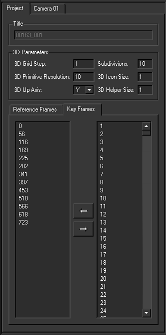
When you create your tracking project, and you’re planning to use the camera track in a software package with a Z axis pointing upwards, such as 3ds Max, make sure your up axis is set to Z. If you leave it on Y, you can fix it later on in 3ds Max by putting your Camera in a Group with a zero pivot point, rotating that group, and rotating the exported tracking keys as well around the world center.
It is recommended to place tracking points in straight physical lines, the spacing inbetween the points does not matter. If the tracking points have been placed on a line (at least four tracking points per line) it can be configured in MatchMover which will take advantage of that knowledge and be more capable of reducing noise in the position of these points, resulting in more stable tracking results. If you know the exact positions and measurements between points, assigning this information to those tracking points will allow MatchMover to do a much more precise and correct calculation of your camera position in relation to these points.
Also of importance is that points are placed nearby and far off, so that the tracking software can derive the depth information from the paralax of the footage. In the screenshot above, for example, there are multiple lines of points on the ground nearby, as wel as four points on a line on the building far off. To place a tracking point, press the button with the tracking line.
Afterwards you scroll in 2D mode (that is, when the button 3D is visible) to the frame in your footage where the point appears on screen for the first time. Then you hold your mouse button down on the place where the point is to be placed, and you can further correct the exact position in the zoom window that appears. Release your mouse button to place the point.
Now trough the rightclick menu on the track in the 2D scene, or on the key in the track view, set the point to Begin.
Thereafter you do the same on the frame where the point leaves the scene, and set this point to End.
Then you place various points on frames inbetween these, to help the tracker follow the point and not leave it’s path. Do not place any points when you’re not perfectly certain of their exact location in the frame. Avoid placing points in blurry frames.
And simply press the button on the top toolbar to automatically let it find the point in the rest of the frames.
If there are any issues with the track, this will appear in red on the track view, on these frames you should place some extra keys in the right location by moving the crosshair in the bad frame to the right position in the 2D view, and running the tracking again.
When the circle next to the track is red, it is best to throw away the track, and try somewhere else in the footage. In case it’s yellow, it’s possible that this track may give problems.
To set up relations between various tracks, right click on the Point Relations folder and create a new relation.
The relations can be set to Line or equal X, Y or Z coordinate. Using Z axis up, points on the ground plane should all be set in one relation of equal Z. It is also possible to configure the exact value of a specific plane, so that the coordinate system can be placed accordingly.
Once you have enough tracks (about eight to start, aim for about sixty eventually) in the scene, you should try running the Solve for Camera functionality.
If all your tracking points turn red, it means you have a bad track that’s breaking everything.
Try disabling the tracking points that have a lot of yellow, or that are generally poorly tracked, until everything looks fine. A tracking point can be disabled by turning off Used for 3D Solving.
Once all of your tracking keys are good, and you’ve done the Solve for Camera again, all of the circles will have turned green. A few yellow ones won’t hurt much.
By pressing the button 3D (topleft in the 2D view) you go to the 3D view.
Press the camera fix button topleft to correctly orient the camera with the footage.
If the tracking went well, you will see planes and lines appear on the Point Relations that you have set up.
To create a coordinate system, you have to make sure that you have properly tracked points on your ground plane that are appropriately oriented. Optimally two axes (depth and side) on the ground plane, with relations configured on all these tracks as the ground plane. All points directly on the X axis have an equal Y value as well, and all points directly on the Y asix have an equal X value.
To create a coordinate system on this ground plane, go to the New Coordinate System menu.
Set the right parameters, and hit Apply. Possibly do another Solve for Camera.
If the coordinate system was set up somewhat correctly, you’ll see something in this style.
To place a number of test objects in the scene, go to New Primitive and choose a shape. With a few primitives you can verify if the scene is stable. Place them at the right height and position around some objects, and see if they follow.
You can scale and move this shape with the control points that are visible in the 3D view.
Another bit of importance, under Project there is a tab Reference Frames and Key Frames. Make sure these lists only contain stable frames. Frames containing keys with an unsure position have to be removed from here. A shorter and more correct list will solve the camera much faster as well. Make sure each track appears in at least three frames listed under keyframes, though.


One thought on “Camera tracking using manually placed tracking points (Autodesk MatchMover)”